Short-er Circuits: Under Hood Wiring Revision

You might have noticed that there’s A LOT of wires in the diagram, right? Well, you’re not wrong. The diagram represents exactly how my truck’s engine bay was wired up – the actual number of individual wires, the actual relay and switch locations, and even the actual position/routes that each of the related wires takes through the vehicle. The reason for all of these is due to the fact that each electrical accessory (The PIAA spot lamps, Rigid Fog LEDs, Blue Sea fuse block, Xterra switch, etc., etc.) was installed at different times during the last 7 years of owning my truck. Not shown above is the ridiculous amount of split wire loom, electrical tape, heat shrink tubing, and zip ties also used! Anyhow, at least I made sure to keep it organized when I added each accessory (there was a method) but nonetheless it was still a ton of wiring.
The primary cause of all of this was the location I chose for the Blue Sea fuse block; I installed the Blue Sea fuse block where many people have with the same vehicle – on top of the OEM engine fuse box which was located on the right side of the engine bay. The issue here is that the main grommet in the firewall that allows the main engine harness to pass through (along with all of the aftermarket wiring) was located on the LEFT side of the engine bay. Since many of the accessories up front were positioned at the leading edge of the engine bay, it made the most sense to run the accessory wiring from the left side of the engine bay (where the firewall opening is), up to the front bumper area, cross it over to the right side of the engine bay, then back to the Blue Sea fuse block. The relays for each accessory were placed in separate locations relative to where I could find a decent, accessible spot.

To be honest, for a couple of years now I knew that one day I would want to revise the whole wiring situation (it’s just the way I am) and early this year the thought became the start of a revision project thanks one day to a sweet 20% Amazon coupon leading me to purchase this:
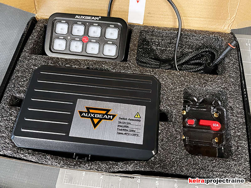
The Auxbeam system features an integrated fuse/relay junction box where most of the accessory connections are made. Because of that, before I tackled the wiring I had to first figure out a location for the Auxbeam junction box, so I’d have the target for all the revised wiring to aim for (The Auxbeam system itself will get its own dedicated post once I’ve completed the install.)
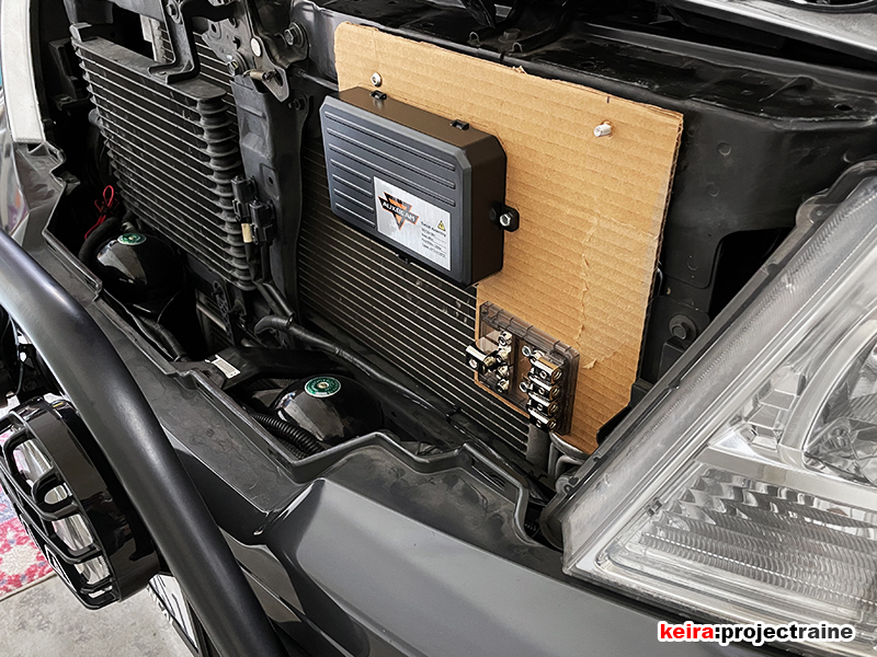
FUN FACT: plain recycled cardboard box panels are great for figuring out panel sizing and location. After trying a few different spots, I decided to mount the Auxbeam junction box behind the center grill, as high up as possible:
Here we go with the Dremel again, this time it was to cut down a sheet of textured Kydex panel that would serve as the mounting point for the Auxbeam junction box:

Before going further I temporarily connected the switch panel and some power/ground to do a quick “power on” test:

With the Auxbeam junction box in place, the next step was to tackle the rewiring (the bulk of the project). Before adding new components, I had to unravel the existing wire looms, confirm that I knew the purpose of each wire, and then formulate the wiring plan with the target being to eliminate as much waiting as possible. I started up front with the forward lights:

…and the old main wiring harness that ran through the firewall:

…and the wiring that ran from the separate PIAA and Rigid light relays:


…also time to remove the Blue Sea fuse block and DB Link fuse holders:


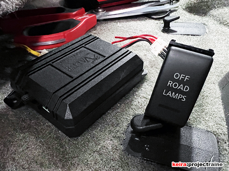
…Goodbye to one of my first electronic mods on my truck, the OEM Nissan Xterra “Off Road Lamps” Switch + DEI latching module (it still works too):


With the old wiring out, the next step was to mount the main components and main wiring in their respective locations – I can’t wire up all of the accessories if I don’t have these components installed first… so pretty much what this diagram is showing:

Coming off the battery, I found that there was enough room on the battery tray to mount the InstallGear ANL fuse holder:

Larger 2-AWG cable ready to attach to the battery terminal bolt:
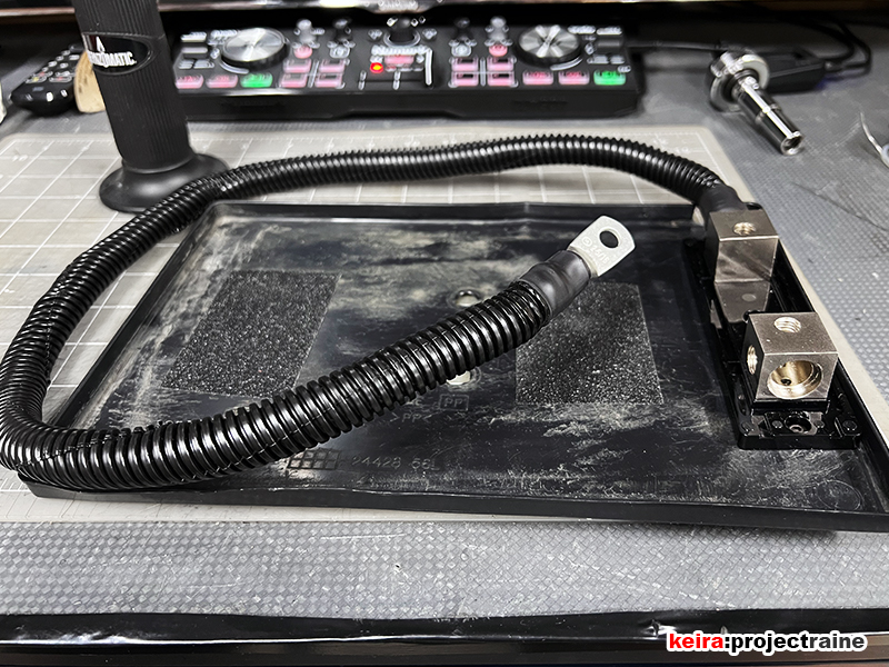
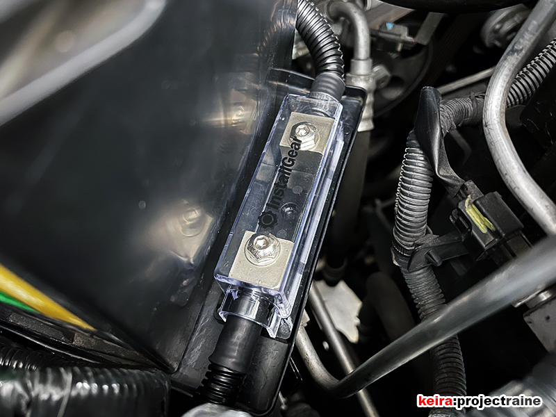
The ANL fuse holder fits perfectly here. I chose this location so that the fuse holder was initially out of sight (compared to the old location on top of the engine bay fuse box), but at the same time was easily accessed if needed:
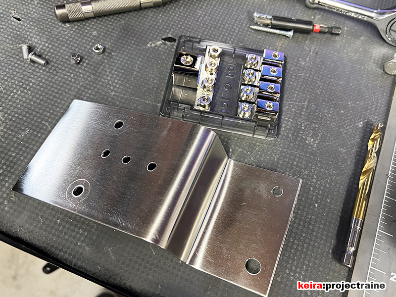
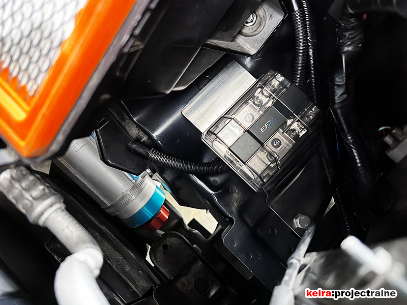
Now on to the EFX 4-way distribution block. This one took longer than expected, mostly because I could not find a place along the left-inner fender area where I initially wanted to position it. However, after taking a break for lunch, suddenly I decided on a new location and a test fit confirmed the new idea. To mount the distribution block, I had to fab up a stainless steel metal plate that I bent into shape:
Made the power cable connections (2 shown here):

…and bolted the mounting plate (with EFX distribution block attached) to the chassis, just in between the air filter box and left headlamp. Again, this mounting spot meant that initially, the distribution block was out of plain sight – yet easily accessible when needed:
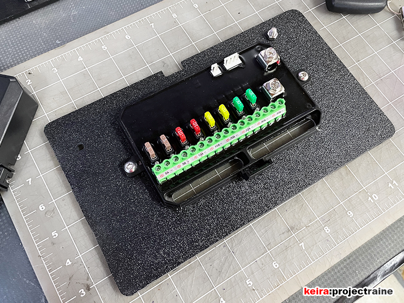
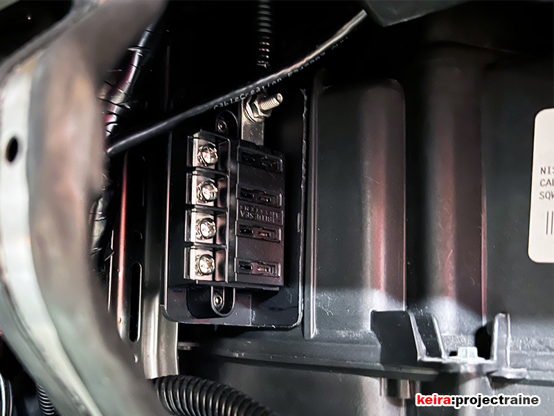
With the EFX distribution block in place, I connected the main power cable from the battery, the Auxbeam power cable, the Alpine PDX-V9 power cable, and the third power cable for the BLue Sea fuse block. Speaking of – on to the inside, to install the new Blue Sea Systems 4-terminal fuse block. I also made a custom mounting plate for this, using scrap plastic that had a 90-degree angle to it:

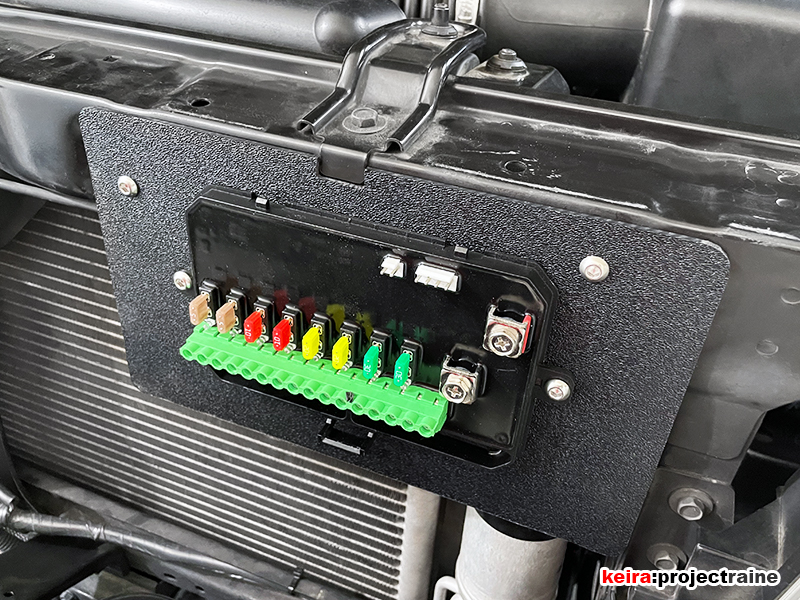
…which allowed me to attach the mounting plate to the HVAC enclosure. This location if you can’t tell is actually behind the lower glove box – again, initially out of sight. However, I can drop the glovebox easily (like what you do when changing the cabin filter) and I get instant access to this fuse block. You can also see the 8-AWG cable connected at the top, which comes from the EFX distribution block:

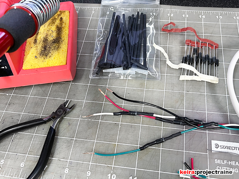
Had to do some prelim diode soldering , pretty basic stuff really:
Testing the wiring lengths to connect to the Auxbeam relay module. The right side was twisted first, then each wire was connected afterward; then I did the left side in reverse by connecting each wire first, then twisting them together afterward. I like the left side better:

As for that “ingredient” I mentioned earlier, it was this: Deutsch DT Series Connectors! While browsing for electrical parts, I discovered these OEM-type high-quality connectors, and they actually fit perfectly with what I wanted to do with the wiring revisions! I ended up buying a 152-piece set:

When the DT plug kit arrived, I took a look at the parts and incorporated them into my wiring scheme with specific groups to make future additions organized and easy:

Prepping the wire ends, this took time to get all of the pin connectors onto each wire, but the job itself was easy and not difficult at all (just repetitive!):

Some clicking and some snapping next, and we have organized, OEM-looking wiring harnesses assembled. I wanted to incorporate plugs into the rewire so that it would be much easier to add more electronics and/or upgrade certain things without having to do the wire strip-and-splice method that people usually do when adding on things after the initial installation:

The DT plugs are double-sealed to be waterproof, and connect together with a very satisfying feel:

The only hint from the outside is if you see the Auxbeam relay module that sits behind the front grill:

BONUS PICS:
…look at all of the existing wiring that I got to get rid of when switching to the Auxbeam relay panel: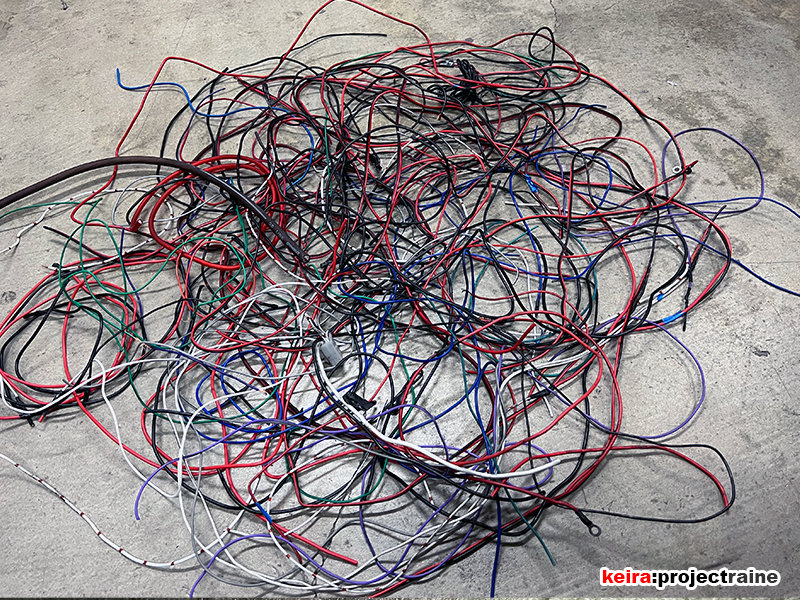
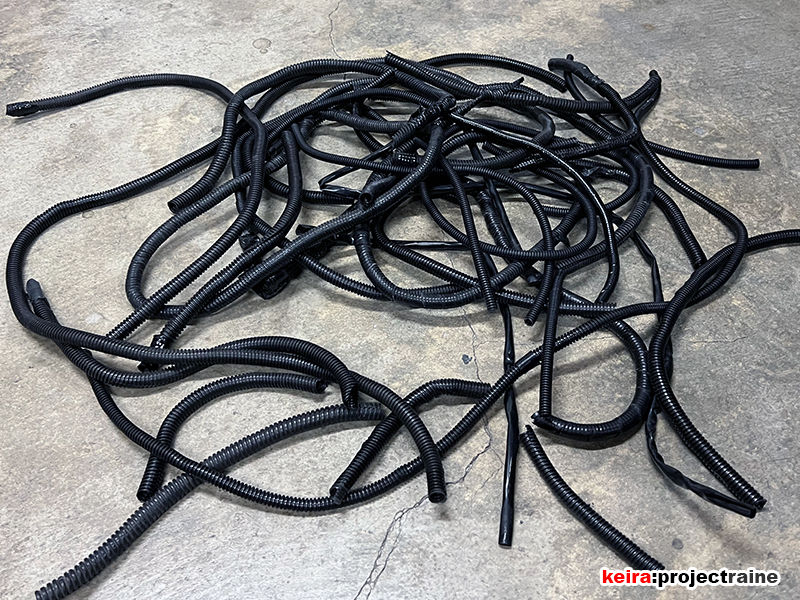
…and of course, all of the extra wiring loom as well that was removed:
…I did manage to salvage some good components, probably going to sell them since they still work:
